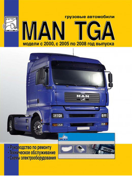
Content
Changes in the design of the MAN TGA (2000 - 2005)
- Cab
- Dashboard BASELINE (EURO 2, 3 and 4), left-hand drive vehicle
- Multifunction steering wheel
- Vehicle menu, MAN audio system and MAN car phone
- Retarder brake
- Engine brake, MAN PRITARDER, Transmission brake (INTARDER) and MAN BRAKEMATIC system
- Fixed engine brake
- Adjustable engine brake
- MAN PRITARDER
- Transmission brake intarder (secondary retarder)
- MAN BRAKEMATIC
- Gearboxes
- MAN COMFORTSHIFT
- MAN TIPMATIC
Engines
- Engine Specifications
- Components and systems of engines
- COMMON RAIL system
- Crankcase
- Cylinder liners
- Carter
- Crankshaft
- Flywheel
- Connecting rod
- Pistons
- Cylinder head and valve actuator
- Nozzle, nozzle body
- Nozzle body
- Valve actuator
- EVB system (EXHAUSE VALVE BRAKE)
- Exhaust system / intake
- Gas distribution mechanism
- Camshaft
- V-belt drive
- Adjustable fan support
- Compressor
- Gas distribution mechanism of diesel engines
- EDC MS 6.1 system
- Installation of a "lifting sliding" injection pump
- Fuel treatment center (KSC)
- Water separator and fuel filter
- Engine oils
- Engine lubrication system
- Oil level sensor with thermocouple
- Regulator "oil level indicator"
- Aspiration
- Turbocharger with "WASTE GATE" (510 hp engine)
- Boost pressure
- Turbocharger
- Charge air cooler (intercooler)
- Cooling system
- WR retarder
- Viscous hydraulic clutch
- Fan clutch
- Electric torch starting aid TGA
- Starter control
- Engine features
- General information about engines D 2066 LF
- Technical data for engines D 2066 LF
- Flywheel side engine
- Engine top view
- Front attachments
- D 2066 LF engine, belt drive side
- Cross section D 2066 LF engine
- The advantages of the COMMON RAIL injection system
- Water flow diagram
- Prevention of accidents when working with engines equipped with COMMON RAIL injection system
- Working with the COMMON RAIL system
- Thermowell kit for fuel line connections
- COMMON RAIL with EDC 7 engine control
- Fuel supply system
- Fuel supply diagram for MAN D 20 engine
- High pressure pump
- Fuel pump
- High pressure pump structure
- Removal and installation of the high pressure pump in in-line engines
- "RAIL" with pressure limiting valve and pressure sensor
- CR injector
- Injection stages
- Changes in combustion pressure with and without pre-injection
- Speed and position sensors
- Components and systems of engines
Engines D2066 EURO 4
- Engine electrical equipment
- Cooling system
- Fan
- Fan drive
- Coolant manifold
- Thermostat
- Thermostat housing
- Coolant pump
- Distributor housing
- Coolant heating system
- Optional equipment
- 1 cylinder air compressor
- 2-cylinder air compressor
- Starter
- Belt drive
- Generator
- Air conditioning compressor
- COMMON RAIL System
- Pressurization system
- Air intake and exhaust system
- Cylinder head
- Valve clearance
- Valve stem seals
- Rocker arms
- Timing mechanism
- Timing gears
- Lubrication system
- Crankshaft oil seals
- Crank mechanism
- Crankcase
- Additional PRITARDER retarder
Clutch
Gearboxes
- Gearboxes ZF 16 S 181 DD, ZF 16 S 181 OD, ZF 16 S 221 DD
- Planetary gear control system
- Diagnostics of gearbox faults
- Removing and installing gearbox
- Gearbox servo
- Removing and installing rear crankcase
- Disassembly and assembly of the ERU planetary gearbox
- Disassembly and assembly of the gearbox
- Oil pump
- Pneumatic gearbox drive
- Gearbox and servo pairing diagram
- Gearbox ZF 9 S 109 DD
- ZF gearboxes with hydraulic INTARDER retarder, modifications 16 S 181 DD / OD - 16 S 221 DD
- Gearboxes EUROTRONIC AUTOMATED 12 AS 2301 DD AND 16 AS 2601 DD / OD
- Gearboxes EUROTRONIC AUTOMATED 12 AS 2301 DD - 16 AS 2601 DD / OD with INTARDER retarder
- Gearbox ZF 16 S (NEW ECOSPLIT)
- Gearbox ZF 12 AS (AS TRONIC)
Steering
Front axle
Rear axle
- Rear axle HPD-1382
Suspension
Braking system
- Front brakes
- Rear brakes
- Disc brake SN 7000
Maintenance
- Electrical equipment and air conditioning
- Diagram 1 (Start): Power / launch system
- Diagram 1 (End): Power / trigger system
- Diagram 2: Powering the Central Computer
- Diagram 3: From INTARDER / EBS / ECAS
- Diagram 4: Retarder / from the vehicle's on-board computer / weight
- Diagram 5: Wipers / washers
- Diagram 6: Heater Fan
- Diagram 7: Cigarette lighter
- Diagram 8: Ashtray lighting
- Diagram 9: Gear Lever / Vehicle On-Board Computer Diagnosis
- Diagram 10: Accelerator pedal unit
- Diagram 11: + 15V power supply
- Diagram 12: Instrument cluster / tachograph
- Diagram 13: Side lights
- Diagram 14: Side lights
- Diagram 15: Turning on the headlights
- Diagram 16: low / high beam headlights
- Diagram 17: Headlamp leveling (for D2R headlights)
- Diagram 18: Rear Fog Lights
- Diagram 19: Fog lamp / rear fog lamp chain
- Diagram 20: Fog lamps / high beam headlamp (floodlight)
- Diagram 21: Brake light
- Diagram 22: Parking light
- Diagram 23: Reversing light
- Diagram 24 (Start): direction indicators
- Diagram 24 (End): direction indicators
- Legend on electrical diagrams
Abbreviations
Electrical circuits MAN TGA 2000 thru 2008 (+ restyling 2005)
Typically, users of our site find this page for the following queries:
wiring diagram MAN TGA, fuses MAN TGA, motor wiring diagram MAN TGA, color wiring diagram MAN TGA
Sorry, the article is only available in Russian.
To read the article, you need to change the language on the site.


