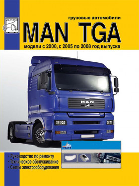
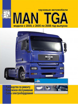
MAN TGA 2000 thru 2008 (+ restyling 2005), repair e-manual (in Russian)
Only original manuals
Available immediately after payment
Full compliance with the paper edition
100% protection of your payments
Publisher: © "Diez"
ISBN: 978-5-903883-95-0
Number of pages: 432
Format: file PDF
About the manual
Engine type: D 2866 / 2876
In the manual you will find
- Instructions for repair of various vehicle components
- Information on self-service car
- Information on the design of the car and how to prevent failure
- The information for the trip to the service station, if the self-repair is impossible
Content
Changes in the design of the MAN TGA (2000 - 2005)
- Cab
- Dashboard BASELINE (EURO 2, 3 and 4), left-hand drive vehicle
- Multifunction steering wheel
- Vehicle menu, MAN audio system and MAN car phone
- Retarder brake
- Engine brake, MAN PRITARDER, Transmission brake (INTARDER) and MAN BRAKEMATIC system
- Fixed engine brake
- Adjustable engine brake
- MAN PRITARDER
- Transmission brake intarder (secondary retarder)
- MAN BRAKEMATIC
- Gearboxes
- MAN COMFORTSHIFT
- MAN TIPMATIC
Engines
- Engine Specifications
- Components and systems of engines
- COMMON RAIL system
- Crankcase
- Cylinder liners
- Carter
- Crankshaft
- Flywheel
- Connecting rod
- Pistons
- Cylinder head and valve actuator
- Nozzle, nozzle body
- Nozzle body
- Valve actuator
- EVB system (EXHAUSE VALVE BRAKE)
- Exhaust system / intake
- Gas distribution mechanism
- Camshaft
- V-belt drive
- Adjustable fan support
- Compressor
- Gas distribution mechanism of diesel engines
- EDC MS 6.1 system
- Installation of a "lifting sliding" injection pump
- Fuel treatment center (KSC)
- Water separator and fuel filter
- Engine oils
- Engine lubrication system
- Oil level sensor with thermocouple
- Regulator "oil level indicator"
- Aspiration
- Turbocharger with "WASTE GATE" (510 hp engine)
- Boost pressure
- Turbocharger
- Charge air cooler (intercooler)
- Cooling system
- WR retarder
- Viscous hydraulic clutch
- Fan clutch
- Electric torch starting aid TGA
- Starter control
- Engine features
- General information about engines D 2066 LF
- Technical data for engines D 2066 LF
- Flywheel side engine
- Engine top view
- Front attachments
- D 2066 LF engine, belt drive side
- Cross section D 2066 LF engine
- The advantages of the COMMON RAIL injection system
- Water flow diagram
- Prevention of accidents when working with engines equipped with COMMON RAIL injection system
- Working with the COMMON RAIL system
- Thermowell kit for fuel line connections
- COMMON RAIL with EDC 7 engine control
- Fuel supply system
- Fuel supply diagram for MAN D 20 engine
- High pressure pump
- Fuel pump
- High pressure pump structure
- Removal and installation of the high pressure pump in in-line engines
- "RAIL" with pressure limiting valve and pressure sensor
- CR injector
- Injection stages
- Changes in combustion pressure with and without pre-injection
- Speed and position sensors
- Components and systems of engines
Engines D2066 EURO 4
- Engine electrical equipment
- Cooling system
- Fan
- Fan drive
- Coolant manifold
- Thermostat
- Thermostat housing
- Coolant pump
- Distributor housing
- Coolant heating system
- Optional equipment
- 1 cylinder air compressor
- 2-cylinder air compressor
- Starter
- Belt drive
- Generator
- Air conditioning compressor
- COMMON RAIL System
- Pressurization system
- Air intake and exhaust system
- Cylinder head
- Valve clearance
- Valve stem seals
- Rocker arms
- Timing mechanism
- Timing gears
- Lubrication system
- Crankshaft oil seals
- Crank mechanism
- Crankcase
- Additional PRITARDER retarder
Clutch
Gearboxes
- Gearboxes ZF 16 S 181 DD, ZF 16 S 181 OD, ZF 16 S 221 DD
- Planetary gear control system
- Diagnostics of gearbox faults
- Removing and installing gearbox
- Gearbox servo
- Removing and installing rear crankcase
- Disassembly and assembly of the ERU planetary gearbox
- Disassembly and assembly of the gearbox
- Oil pump
- Pneumatic gearbox drive
- Gearbox and servo pairing diagram
- Gearbox ZF 9 S 109 DD
- ZF gearboxes with hydraulic INTARDER retarder, modifications 16 S 181 DD / OD - 16 S 221 DD
- Gearboxes EUROTRONIC AUTOMATED 12 AS 2301 DD AND 16 AS 2601 DD / OD
- Gearboxes EUROTRONIC AUTOMATED 12 AS 2301 DD - 16 AS 2601 DD / OD with INTARDER retarder
- Gearbox ZF 16 S (NEW ECOSPLIT)
- Gearbox ZF 12 AS (AS TRONIC)
Steering
Front axle
Rear axle
- Rear axle HPD-1382
Suspension
Braking system
- Front brakes
- Rear brakes
- Disc brake SN 7000
Maintenance
- Electrical equipment and air conditioning
- Diagram 1 (Start): Power / launch system
- Diagram 1 (End): Power / trigger system
- Diagram 2: Powering the Central Computer
- Diagram 3: From INTARDER / EBS / ECAS
- Diagram 4: Retarder / from the vehicle's on-board computer / weight
- Diagram 5: Wipers / washers
- Diagram 6: Heater Fan
- Diagram 7: Cigarette lighter
- Diagram 8: Ashtray lighting
- Diagram 9: Gear Lever / Vehicle On-Board Computer Diagnosis
- Diagram 10: Accelerator pedal unit
- Diagram 11: + 15V power supply
- Diagram 12: Instrument cluster / tachograph
- Diagram 13: Side lights
- Diagram 14: Side lights
- Diagram 15: Turning on the headlights
- Diagram 16: low / high beam headlights
- Diagram 17: Headlamp leveling (for D2R headlights)
- Diagram 18: Rear Fog Lights
- Diagram 19: Fog lamp / rear fog lamp chain
- Diagram 20: Fog lamps / high beam headlamp (floodlight)
- Diagram 21: Brake light
- Diagram 22: Parking light
- Diagram 23: Reversing light
- Diagram 24 (Start): direction indicators
- Diagram 24 (End): direction indicators
- Legend on electrical diagrams
Abbreviations
Write a review
Your Name:
Your Review:
Customers reviews
Руководство купил для ремонта коробки передач. Вышло намного дешевле, нежели ехать на СТО.


