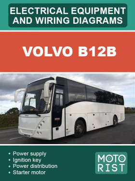
Volvo B12B bus, wiring diagrams
About the manual
Engine type: DH12E
In the manual you will find
- wiring diagram for Volvo B12B
- electrical equipment Volvo B12B
About the manual
Engine type: DH12E
In the manual you will find
- wiring diagram for Volvo B12B
- electrical equipment Volvo B12B
Content
Example of wiring diagram
Power supply
Ignition key and power distribution
Starter motor and alternators, B7R
Starter motor and alternators, B9L
Starter motor and alternators, B9S
Starter motor and alternators, B12B
Starter motor and alternators, B5L
VECU, vehicle ECU
VECU, vehicle ECU
BBM, body builder module
BIO, BUS I/O
Instrument cluster, BIC
Instrument cluster, VDV
Tachograph
Alco Loc
Engine interface, BH / B7
Engine interface, B9
Engine interface, B12
DNOX2 system
Oilmaster
FTM, fuel tank monitor, CNG
gearbox, Volvo I-shift
Gearbox, ZF Ecolife
Gearbox, ZF Ecomat
Gearbox, Voith DIVA5
EBS, electronic brake system
APBE, AUTO. P-brake evacuation
ECS, air suspension
AMECU, artic pusher
RAS ECU, artic puller
LCM, light control module
Front light
Front light, xenon relays
Side light
Side light, artic
Rear light
Rear light, artic / hybrid
Rear light, artic
Wiper / washer / horn
Advanced information centre
Dynafleet
FMS gateway
Radio switches
Hybrid traction voltage
Hybrid system
ESS heater / charger
Hybrid power steering
Extensions, artic pusher, B9L
Bus, J1587 / J1708
Bus, J1939-1
Bus, J1939-2 and J1939-3
Bus, J1939-7
Bus, J1939-7 Hybrid
Bus, DBUS
Body interface
Ground
Bill of material/component list
Component placement
Electrical distribut unit, chassis
Relay
Fuses
Intermediate connector pieces
Control units
Diagnostic connector
Electrical distribution units


