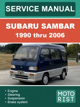
Subaru Sambar 1990 thru 2006, repair e-manual
About the manual
Engine type:EN07
Engine capacity: 0.7 l.
In the manual you will find
- Step-by-step guide to repair various components and assemblies
- Self-care and maintenance instructions
- Car design and prevention information
- Information for a trip to the service station, if self-repair is not possible
Content
Vehicle identification
- VIN class breakdown
- Engine and transmission decoding
- Engine-transmission combination charts
- Vin and code locations
- Jacking positions
- Tire size and air pressure guide
General maintenance and tune up
- Engine specifications
- Testing equipment
- Battery and coolant
- Oil and filter including supercharger
- Air and fuel filter
- Spark plugs
- V- belts
- Valve adjustment
- Vacuum hose
- Distributor point settings
- Timing
- Idle setting
- CO-HC levels and adjustment
- Engine vacuum and troubleshooting
- Main relay location guide
Suspension
- Front suspension components
- Rear suspension components
- Front and rear alignment
- Camber and caster settings
- Front strut removal and replacement
- Traverse link
- Rear shock absorber remove and replace
Steering
- Specifications and diagram
- Exploded component view (steering column)
- Exploded component view (rack and pinion)
- Steering column removal / disassembly /assemble / install Steering gear box
- Rack and pinion overhaul
- Tie rods
Brake system
- Bleeding brake system (air)
- Parking brake adjustment
- Master cylinder system
- Brake booster
- Disk brake and caliper overhaul
- Rear brake drum system overhaul
- Parking brake cable system
- Complete brake line system
Engine coolant and cooling system
- Coolant system specifications and capacities
- Coolant system components diagram
- Coolant system radiator components diagrams
- Engine room fan system
- Troubleshooting chart
- Coolant line diagrams (chassis mount)
- Water pump
- Engine room fan circuit
- Cooling master control unit and circuit
Air — fuel system — exhaust
- Air intake system (carbureted)
- Air intake system (fuel injected-supercharged)
- Air cleaner and air intake sensor
- Intake manifold (carbureted)
- Complete fuel system specifications
- Carburetor adjustments and breakdown
- Fuel tank
- Fuel system EMPI (fuel injected vehicles)
- Fuel pump-pressure regulator-knock sensot
- Fuel injection-air/water temp sensors-O2 sensor
- Exhaust truck-van
Starter and alternator
- Starter specifications hitachi series-mitsubishi series
- Starter overhaul diagrams
- Alternator specifications- mitsubishi series-denso series
- Alternator diagram
Engine and transmission removal
- Complete engine and transmission removal
Engine overhaul
- Engine disassembly
- Block inspection
- Cylinder inspection
- Piston inspection including oversize pistons
- Block deck-journal and bore sizes
- Piston rings and installation positioning
- Connecting rods
- Crankshaft and journals
- Journal details and clearances
- Crankshaft oil seals
- Block assembly
- Piston installation
- Oil pump
- Cylinder head and timing belt system
- Valve rocker assembly
- Camshaft specifications and clearances
- Camshaft installation and oil seal
- Cylinder head — valve springs- valves
- Valve guides- valve details
- Oil pump overhaul
- Oil pressure switch
Transmission and differential 2WD - 4WD
- Gear shift system
- TM 60 series 2WD clutch housing — main case - side case
- TM 60 series 2WD main shaft-drive pinion- reverse idler shaft TM 60 series 2WD shift and select system
- TM 60 series 2WD differential
- TM 60 series selective 4WD transmission case assembly
- TM 60 series selective 4WD shifter and selector system
- TM 60 series selective 4WD drive pinion-main shaft-reverse idler
- TM 60 4WD differential
- TM 60 4WD diff-lock differential option
- TM 60 4WD diff-lock side cover assembly
- TM 60 selective 4WD transfer extension
- Clutch and pressure plate specifications
- Clutch system diagram
- Clutch cable adjustment
- Release bearing and fork
- Clutch disk — flywheel — pressure plate
- Clutch assembly
- Axel shaft system
- Axel shaft identification and type
Electrical diagrams and schematics
- General harness locations
- Truck full main harness and connection codes
- Connection codes explained (truck-van)
- Van full main harness and connection codes
- Engine and transmission harness and connections
- Engine and transmission harness code breakdown
- Front component (main) harness dash-front lighting
- Front component (main) connector breakdown
- Electrical schematic breakdowns
- Turn signal and hazard
- Stop lamp circuit
- Lighting circuit (headlights-running lights)
- Lighting circuit tail assemblies and illumination lamps
- Engine control and fuel pump circuits
- Charging system
- Engine room and radiator fan (van and special trucks)
- Engine radiator fan (basic vehicle)
- Radio (audio) circuits and cigarette lighter
- Fuel gage and sending unit
- Full time 4WD control circuits
- Selective 4WD control circuits
- Diff-lock control circuits
- EMPi engine control management system part (fuel injection)
- Windshield wiper system front and rear
- Rear defogger circuit