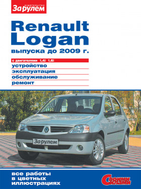
Renault Logan until 2009, repair e-manual (in Russian)
About the manual
Engine type: K7J / K7M
Engine capacity: 1.4 / 1.6 liters.
Power: 75/87 hp
In the manual you will find
- Instructions for repair of various vehicle components
- Information on self-service car
- Information on the design of the car and how to prevent failure
- The information for the trip to the service station, if the self-repair is impossible
Content
Conventions
Model history
Logan in Russia and in the world
General information
- Overall dimensions of the car
- Vehicle specifications
- Vehicle data sheet
- Execution options
Equipment and controls
- Location of controls and appliances
- Instrument cluster
- Car keys
- Ignition switch (lock)
- HVAC control unit
- Headlight beam direction regulator
- Switches
- Gearshift paddles
- Passenger airbag switch
- Interior rearview mirror
Operating instructions
- Oversized cargo transportation
- Wheels and tires
- Features of winter operation
- Repair in transit
- Wheel replacement
- Replacing the headlight lamp in the headlamp, the combination side-marker lamp and the brake light in the rear light
- Starting the engine from the battery of another car (lighting)
- Car towing
Safety precautions for maintenance and repair
Maintenance
- Location of the main components and assemblies of the car
- Checking the car
- Maintenance Schedule
- Checking the condition of wheels and tires
- Replacing the windshield wiper blades
- Checking engine oil level
- Changing engine oil and oil filter
- Checking the level and adding coolant
- Coolant replacement
- Checking the level and adding oil to the gearbox
- Checking the fluid level in the reservoir of the hydraulic brake system
- Replacing the fluid in the hydraulic brake system
- Bleeding the hydraulic brake system
- Checking the fluid level in the power steering reservoir
- Replacing the accessory drive belt
- Checking the condition and replacing the timing belt
- Replacing spark plugs
- Replacing the fuel filter
- Replacing the air filter element
- clutch release adjustment
- Checking the condition of the brake system
- Checking the condition of the chassis and transmission
- Checking steering status
- Car repair
Engine
- Design description
- Replacing the cylinder head gasket
- Checking and adjusting the thermal clearances in the valve actuator
- Replacing the camshaft oil seal
- Exhaust manifold gasket replacement
- Replacing the front crankshaft oil seal
- Replacing the crankshaft rear oil seal
- Replacing low oil pressure switch sensor
- Crankcase gasket replacement
- Removing the oil pump
- Powertrain support replacement
- Removing and installing engine or powertrain
Engine management system
- Design description
- Removing the electronic control unit
- Removing the crankshaft position sensor
- Removing the coolant temperature sensor
- Removing the throttle position sensor
- Removing the knock sensor
- Removing the intake air temperature sensor
- Removing the absolute air pressure sensor
- Removing the oxygen concentration sensor
- Removing the speed sensor
- Ignition coil removal
Power System
- Design description
- Removing and disassembling the fuel module
- Removing the air filter
- Removing the fuel rail and injectors
- Removing the idle speed regulator
- Throttle removal
- Removing the intake manifold, replacing the gaskets
- Removing the fuel tank
- Removing the adsorber of the vapor recovery system
- Replacing the throttle cable
Cooling system
- Design description
- Removing and checking the thermostat
- Removing the radiator fan
- Removing the radiator
- Removing the coolant pump
- Removing the expansion tank
Exhaust system
- Design description
- Replacing the suspension cushion
Exhaust systems
- Removing the exhaust system
- Replacing exhaust system components
Grip
- Design description
- Clutch release cable replacement
- Removing clutch parts
Gearbox
- Design description
- Replacing shift lever bushings
- Removing the gear lever
- Gearbox control link removal
- Replacing the right wheel drive gland
- Removing and installing gearbox
Front wheel drive
- Design description
- Removing front wheel drives
- Replacing the mud cover of the right-hand drive inner hinge
- Replacing cover and bearing for left-hand drive inner hinge
- Replacing the mudguard cover of the outer wheel drive hinge
Front suspension
- Design description
- Removing the shock absorber strut and its disassembly
- Replacing anti-roll bar components
- Lever removal
- Replacing the ball joint
- Removing the subframe
- Front wheel bearing replacement
Rear suspension
- Design description
- Shock absorber removal
- Spring removal
- Replacing the silent block of the beam arm
- Removing the rear suspension beam
- Replacing the rear wheel bearing
Steering
- Design description
- Steering wheel removal
- Steering column removal
- Replacing the tie rod end
- Steering gear cover replacement
- Steering gear removal
- Removing the power steering pump
- Bleeding the power steering system
Brake system
- Design description
- Replacing the brake pads of the front wheels
- Replacing the front wheel brake piston protective cover
- Replacing the brake pads of the rear wheels
- Removing the brake master cylinder
- Removing the check valve of the vacuum brake booster
- Removing the brake servo
- Replacing the front wheel brake hose
- Replacing the front wheel brake disc
- Replacing the wheel cylinder of the rear wheel brake mechanism
- Replacing the brake hose of the rear wheel
- Replacing the parking brake cables
- parking brake adjustment
- Removing the front wheel speed sensor
- Removing the rear wheel speed sensor
- Removing the ABS unit
- Removing the pressure regulator in the brakes of the rear wheels, adjusting the drive
Electrical equipment
- Design description
- Removing relays and fuses
- Replacing immobilizer coil and ignition switch
- Removing the battery
- Removing the generator, replacing the voltage regulator and rectifier unit
- Removing and disassembling the starter
- Replacing the lamps in the headlamp
- Removing the headlamp
- Removing the actuator for headlight beam direction control
- Replacing the fog lamp
- Removing the fog lamp
- Removing the side direction indicator, replacing the lamp
- Removing the reversing light switch
- Removing the taillight, replacing the lamps
- Replacing the lamp in the additional brake signal
- Removal of a lamp of illumination of a back license plate. Replacing the lamp
- Replacing bulbs for interior lighting, removing the lamp
- Removing the trunk light, replacing the lamp
- Removing the steering column switches
- Beeping
- Removing the switches on the dashboard console
- Removing the windshield wiper motor gearbox
- Removing the windshield washer pump
- Removing instrument cluster
- Removing the junction box
- Removing the airbag control unit
- Removing the driver’s airbag
Body
- Design description
- Removing the powertrain protection
- Removing the front bumper mudguards
- Removing the mudguards of the engine compartment
- Removing mudguards and front wheel arch liners
- Removing mudguards and rear wheel arch liners
- Removing the hood lock and lock drive cable
- Removing the front bumper
- Removing the rear bumper
- Removing the front door trim
- Removing the exterior rearview mirror
- Removing the front door glass
- Removing the front door power window mechanism
- Removing the lock and the outer handle of the front door
- Removing the rear door trim
- Removing the rear door glass
- Removing the rear window regulator
- Removing the lock and the outer handle of the rear door
- Removing the tailgate lock
- Removing the floor tunnel lining
- Removing the instrument panel lower trim
- Removing the dashboard
HVAC system
- Design description
- Removing the ventilation, heating and air conditioning control unit
- Heater fan removal
- Removing additional heater fan resistor
- Removing the heater radiator
- Removing air conditioning compressor
Diagnostics of malfunctions
- Engine and its systems
- Transmission, chassis, steering and braking system
- Electrical equipment
Applications
- Tools used in car repair
- Tightening torques for critical threaded connections
- Spark plugs
- Applicable fuels, lubricants and operating fluids
- Lamps used in the car
Schemes of electrical equipment (wiring diagrams)
- Wiring diagrams
- Electronic engine control system diagram
- Connection diagram of the relay mounting block and fuses in the engine compartment (without air conditioning)
- Connection diagram of the mounting block of the relay and fuses in the engine compartment (with air conditioning)
- Connection diagram for the fuse box in the passenger compartment
- Connection diagram of alternator and starter
- Instrument cluster wiring diagram
- Connection diagram for fuel gauge, oil pressure sensor, parking brake switch, brake fluid level sensor
- Vehicle speed sensor connection diagram
- Engine start blocking circuit (immobilizer)
- Engine fan cooling circuit
- Braking signal activation circuit
- Headlight low beam circuit
- Headlamp high beam circuit
- Turn signal light and hazard warning light
- Clearance light circuit
- Trunk lighting activation circuit
- Cigar Lighter Switching Scheme
- Reverse light activation circuit
- Rear fog light switch on circuit
- Lighting box lighting circuit
- Connection diagram of the diagnostic connector
- Windshield Wiper Wiring Diagram
- Scheme of switching on the electrode bug on the front door nickname
- Power window for rear doors
- Connection block connection diagram
- ABS control unit connection diagram
- Connection diagram for ventilation, heating and air conditioning
- Driver airbag connection diagram
- Connection diagram for driver and front passenger airbags
- Rear window deflection circuit
- The connection diagram of the exterior mirrors with electric and electric heating
- Sound signal activation circuit


