I used this manual, it helped me a lot in disassembling and assembling the gearbox
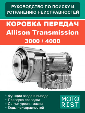
Allison Transmission 3000 / 4000 gearbox, troubleshooting e-manual (in Russian)
Only original manuals
Available immediately after payment
Full compliance with the paper edition
100% protection of your payments
Publisher: © "Motorist"
ISBN: 978-040-000-329-0
Number of pages: 880
Format: file PDF
About the manual
Engine type: diesel
In the manual you will find
- Description of Allison's 4th generation 3000 and 4000 series electronic controls
- Description of the components electronic control system.
- Information on the repair of wires, terminals and connectors.
Content
Foreword
Safety information
- Important safety notice
- Warnings, cautions and notes
- Trademarks used in this manual
- Gear shift terms and gear shift display
General description
- Gearbox
- Transmission control module (TCM)
- Gear selector
- A. Push button shift
- B. Lever type gear selector
- Throttle position sensor
- Speed sensors
- Control module
- Posting
- A. Field wiring
- B. Internal wiring
- Vehicle interface module
- Auto detect function
- A. Retarder
- B. Oil level sensor (OLS)
- C. Throttle position signal source
- D. Engine coolant temperature TRANSID (TID)
Definitions and abbreviations
- Check trans indicator light (check transmission)
- Allison Transmission diagnostic tool
- Abbreviations
General information
- General training required
- Using the troubleshooting guide
- System overview
- Important information for troubleshooting
- Start the troubleshooting process
- TCM Diagnostic procedure
- Reset TCM parameters to support engine information update
- Reset TCM autoselect
Checking the wiring
- Check for open circuits, short circuits between wires and short circuits to ground
- Checking the transmission through connector for open circuits, wire-to-wire shorts, and short to ground
Oil level sensor
- Introduction
- Oil level display (gear selector)
- A. Oil level reading procedure
- Electronic oil level check (Allison DOCTM for PC – service tool)
- A. Oil level reading procedure
Diagnostic trouble codes
- Memory of diagnostic trouble codes
- Read and reset DTC
- System response after registration of diagnostic trouble codes
- Gear shift display indications associated with active DTCs
- Index and description of diagnostic trouble codes
- Troubleshooting diagnostic trouble codes
- A. Starting the troubleshooting process
- B. Arrangement of solenoids
- C. Diagram of diagnostic trouble codes
Input and output functions
- Input functions
- Output function
Troubleshooting process for performance complaints
Applications
- A. Identifying potential wiring problems
- B. Checking the clutch and retarder pressure
- C. Solenoid and clutch table
- D. Wire / connector table
- E. Connector numbers, terminal numbers tool numbers and repair instructions
- F. Throttle position sensor adjustment
- G. Carrying out welding work on the vehicle / interface module for connecting diagnostic equipment
- H. Hydraulic diagram
- J. 3000 and 4000 series equipment wiring diagram
- K. Solenoid resistance table
- L. Electromagnetic interference from external sources
- M. Diagnostic chart - 3000 and 4000 series gearbox hydraulics
- N. ALLISON DOCTM for PC – service tool
- P. Input and output functions
- Q. Thermistor troubleshooting information
- R. SAE J1939 data channel
Write a review
Your Name:
Your Review:


