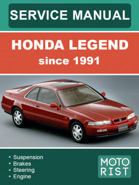
Honda Legend since 1991, repair e-manual
About the manual
Engine type: C32A
Engine capacity: 3.2 l.
Power: 202 hp
In the manual you will find
- Step-by-step guide to repair various components and assemblies
- Self-care and maintenance instructions
- Car design and prevention information
- Information for a trip to the service station, if self-repair is not possible
Content
General information
- Chassis and paint codes
- Identification number locations
- Label locations
- Lift and support points
- Towing
- Preparation of work
- Symbol marks
- Abbreviations
SRS
- Description
- Wiring location
- Warning / caution labels
- Precautions / procedures
Special tools
Specifications
- Standards and service limits
- Design specifications
- Body specifications
Maintenance
- Lubrication points
- Maintenance schedule
Engine removal / lnstallation
Cylinder head/valve train
- Special tools
- Illustrated index
- Cylinder head removal
- Rocker arms and shafts
- Camshaft inspection
- Valve and valve seals
- Valve guides
- Cylinder heads
- Valve spring and valve seals
- Hydraulic tappets
- Camshafts / rocker arms and camshaft seals
- Cylinder head installation
- Timing belt
- Crank / cyl sensor
Engine block
- Special tools
- Illustrated index
- Flywheel and drive plate
- Rod and main bearings
- Pistons and crankshaft removal
- Crankshaft
- Pistons
- Cylinder block
- Piston pins
- Piston rings
- Oil seal
- Crankshaft installation
Engine lubrication
- Special tools
- Illustrated index
- Oil level inspection
- Oil replacement
- Oil filter replacement
- Oil pressure test
- Oil pan removal / lnstallation
- Oil pump illustrated index
- Oil pump removal / lnspection
Intake manifold / exhaust system
- Intake manifold
- Exhaust manifold
- Exhaust pipe and muffler
Cooling
- Illustrated index
- Radiator
- Refilling and bleeding
- Thermostat
- Water pump
Fuel and emission
- Special tools
- Component locations index
- System description vacuum connections
- Troubleshooting
- Pgm-fi/at electronic control unit
- Idle control system
- Fuel supply system
- Air intake system
- Emission control system
- Evaporative emission controls
Clutch
- Special tools
- Illustrated index
- Pedal free play
- Clutch master cylinder
- Slave cylinder
- Pressure plate, clutch disc
- Pressure plate
- Clutch disc
- Flywheel, flywheel bearing
- Pressure plate, clutch disc
Manual transmission
- Special tools
- Maintenance
- Transmission assembly
- Transmission cover
- Transmission housing
- Mainshaft, countershaft, reverse gear shaft
- Mainshaft. Countershaft
- Reverse shift holder, shift fork
- Chango holder, shift fork
- Synchro sleeve. Synchro hub
- Synchro ring. Gear
- Oil pump
- Mainshaft bearing (clutch housing)
- Countershaft bearing (clutch housing)
- Malnshaft/countershaft
- Secondary gear assembly
- Extension shaft
- Oil seal (secondary gear)
- Oil seal
- Taporod rollor bearing
- Bearing preload
- Oil seal
- Mainshaft, countershaft. Reverse gear shaft
- Transmission housing
- 5th gear
- Transmission cover
- Transmission assembly
- Gearshift mechanism
Automatic transmission
- Special tools
- Electrical system
- Electrical troubleshooting
- Hydraulic system
- Lower valve body assembly
- Transmission
- Illustrated index
- Lowor valve body
- Rear cover
- Transmission housing
- Torque converter houslng/valve body
- Valve
- Oil soal
- Oil seal
- Clutch
- Torque converter housing bearings
- Shift coble
- Gearshift selector
- Shift indicator panel
Differential
- Special tools
- Troubleshooting
- Maintenance
- Differential assembly
- Differential
- Differential case
- Drive pinion
- Height adjustment
- Ring gear tooth contact
- Ring gear backlash
Driveshafts
- Special tools
- Driveshafts
- Intermediate shaft
Steering
- Special tools
- Component location
- System description
- Fluid flow diagram
- Steering pump
- Fluid reservoir / filter
- Control valve
- Full-lock unloader system
- Speed sensor
- Troubleshooting
- Maintenance
- Power assist check with car
- Speed sensor replacement
- Steering wheel
- Steering column
- Steering pump
- Steering gearbox
Suspension
- Special tools
- Component location index
- Wheel alignment caster
- Camber
- Wheel measurements
- Bearing end play
- Runout
- Front suspension
- Knuckle / hub replacement
- Lower / upper ball joint boot
- Front damper
- Rear suspension
- Lower / upper ball joint boot
- Rear damper
Brakes (anti-lock brake system)
- Special tools
- Illustrated index
- Pedal height
- Parking brake
- Front brakes
- Front brake pads
- Front caliper
- Front brake disc
- Bleeding
- Master cylinder and brake booster
- Master cylinder
- Brake booster
- Rear brakes
- Rear brake pads
- Parking drum brakes
- Rear caliper
- Rear brake disc
- Parking brake cable
- Anti-lock brake system
- Circuit diagram
- Wiring/connector location
- Alb checker
- Function test
- Wheel sensor signal confirmation
- Anti-lock brake system indicator light
- Symptom-to-system chart
- Flowchans
- Hydraulic system
- Modulator unit
- Solenoids
- Piston
- Power / accumutator / pressure switch unit
- Bleeding
- Air bleeding
- Electronic components
- Control unit replacement
- Relays inspection
- Pulsers / sensors
Body
- Bumpers
- Carpet
- Doors
- Latch
- Glass
- Fuel filler
- Front grille / hood edge protector
- Headliner
- Hood
- Interior trim
- Mirrors
- Mirror glass
- Seats
- Seat belts
- Stereo cassette / radio
- Sunroof
- Trunk
- Lid latch
- Rear window
Heater and air conditioner
- Heater
- Automatic climate control
Automatic climate control
- Special tools
- Illustrated index
- Heater-evaporator door positions
- Air conditioner
- Triple pressure switch
- Fan control unit
- Wiring and connector locations
- Circuit diagram
- Climate control unit
- Signals
- Blower motor
- Evaporator temperature sensor
- Sensor
- Blower
- Heater-evaporator unit
- Recirculation control motor
- Mode control motor
- Air mix control motor
- Max cool motor
- Aspirator fan motor
- Coolant temperature sensor
- A/C service tips and precautions
- A/C system service
- Compressor
- Condenser
- System charging
Electrical
- Special tools
- How to use this section
- Troubleshooting
- Schematic symbols
- Wire color codes
- Relays and control unit locations
- Engine compartment
- Dashboard
- Air conditioner section
- Alternator
- Antenna, power
- Anti-lock brake system section
- Automatic transmission
- Control system section
- Battery
- Blower controls section
- Charging system
- Cigarette lighter
- Clock
- Cruise control
- Fuse box
- Gauges
- Heater controls section
- Horns
- Ignition switch
- High beam indicator
- Safety indicator
- Shift levor position indicator
- Tum signal indicator
- Lights, exterior
- Hazard lights
- Brake lights
- License plate lights
- Parking lights
- Roar fog light
- Rear side marker lights
- Taillights
- Tum signal lights
- Lights, interior
- Coutesy lights
- Dashlights brightness control
- Entry light timer system
- Front spot lights
- Glove box light
- Rear spot lights
- Trunk light
- Vanity mirror lights
- Lighting system
- Locks, power
- Mirrors, power
- Oil lovel warning system
- Opener, trunk
- Power relay inspection
- Power distribution
- Radiator and condenser fan controls
- Relay locations
- Seats, power
- Heater
- Security alarm system
- Spark plugs
- Starting system
- Stereo sound system
- Sunroof
- Supplemental restraint system (SRS)
- Side marker / tum signal / hazard flasher system
- Washer
- Headlights
- Windshield
- Windows, power
- Wlpors, windshield
- Wires, harnesses and connectors
- Wire color codes
- Wiring hamess routing
- Wiring diagrams
Supplemental restraint system
- Component location index
- Circuit diagram
- Wiring locations
- Troubleshooting
- Airbag assembly
- Cable reel
- Dash sensor
- SRS unit


