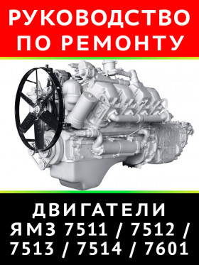
Engine YaMZ-7511.10 / 7512.10 / 7513.10 / 7514.10 / 7601.10, owners e-manual (in Russian)
About the manual
Engine type: YaMZ-7511.10 / 7512.10 / 7513.10 / 7514.10 / 7601.10
In the manual you will find
- Step-by-step guide to repair various components and assemblies
- Self-care and maintenance instructions
- Engine design and prevention information
- Information for a trip to the service station, if self-repair is not possible
Contents
Introduction
General information
- Scope and scope of the publication
- Terms and definitions
- Purpose and features of a complete set of power units
- Powertrain specifications
Engine design and operation
- Cylinder block
- Cylinder head
- Crankshaft
- Flywheel
- Connecting rod
- Crankshaft bearing shells
- Cylinder liner
- Piston
- Piston rings
- Piston pin
- Packing options liner - piston - piston rings
- Gas distribution mechanism
- Camshaft
- Pushers
- Pusher axles
- Push rods
- Valve rocker arms
- Inlet and outlet valves
- Lubrication system
- Power system
- Fuel pump drive
- High pressure fuel pump
- Design and operation of the high pressure fuel pump
- Speed controller
- Basic adjustments provided by the regulator design
- Damper clutch
- Fuel priming pump
- Injectors
- Injectors models 267-02 and 204-50.01
- Injector model 51-01
- Coarse fuel filter
- Fine fuel filter
- Fuel lines
- Aspiration
- Model 122 turbocharger device
- Cooling system
- Water pump
- Fan drive
- Design and operation of the fan friction drive
- Electromagnetic switch
- Liquid-oil heat exchanger
- Electrical equipment
- Generators
- Generator model 1322.3771
- Generator model 1702.3771
- Generator model 6582.3701-03
- Generator model 5702.3701-30
- Starters
- Starter 25.3708-21
- Starter AZF 4581
- Electric torch device
- Tightening torques for main screw connections
Maintenance of engines
Complete engine disassembly procedure
Parsing nodes
- Disassembly of the CPG
- Crankshaft disassembly
- Disassembly of the water pump
- Disassembly of the oil pump
- Fan drive disassembly
- Disassembly of the injection pump drive
- Dismantling the fine fuel filter
- Oil filter disassembly
- Disassembly of the centrifugal oil filter
- LMC disassembly
Assembly of units and assemblies
- Subassembly of the centrifugal oil filter
- Oil filter subassembly
- Subassembly of the fine fuel filter
- Injection pump drive subassembly
- Fan drive subassembly
- Sub-assembly of the oil pump
- Subassembly of the water pump
- Crankshaft subassembly
- ShPG subassembly
- Camshaft subassembly
- Cylinder head subassembly
- Water pump tensioner subassembly
Engine subassembly
- Cylinder block subassembly
- Installing the injection pump drive
- Installing pushers
- Installing oil piston cooling nozzles
- Installing the camshaft (7511.1006010)
- Installing the upper crankshaft main bearing shells
- Pressing in the pins of the crankshaft thrust half rings
- Installing the lower crankshaft main bearing shells
- Installing the crankshaft
- Installing cylinder liners.
- Installing ShPG in cylinder liners
- Installing cylinder heads
- Installing the timing gear cover
- Assembling the cover of the upper block with a fine fuel filter
- Installing the flywheel housing
- Installing the flywheel
- Installing the front support bracket and centrifugal oil cleaner
- Installation of pipes and manifolds
- Assembling the oil pump with pipes
- Installing the oil sump
Final engine assembly
- Installing the tensioner and water pump belt
- Assembling the injection pump with low pressure pipes and installing it on the engine
- Fastening the low pressure pipes to the filter, the plunger pair return pipes and the oil return pipes to the injection pump
- Installing injectors on the engine
- Installation of high pressure pipes and connecting pipe
- Installing the inlet pipe
- Installation of rocker arms of MGR valves
- Installing the oil filter
- Installing the fan drive
- Installing an electric torch device
- Bypass pipe installation
- Installing the branch pipe-bracket on the flywheel housing platform
- Assembling the turbocharger with oil drain pipe
- Installing the turbocharger
- Installation of the connecting pipe
- Installing the cylinder head covers
- Installing the engine on a stand
- Installing the starter and water channel plugs
- Installing an oil-liquid heat exchanger
- Installing the generator
- Installing the union in the cylinder block
- Installing the air inlet tube
- Installing the oil supply pipe to the turbocharger
- Setting the fuel injection advance angle
Technical requirements for fault detection of parts and assembly units
- General technical requirements for engine disassembly
- General technical requirements for fault detection and repair
- Special requirements for components (fault detection cards)
- Group 1001
- Engine mount
- Group 1002
- Cylinder block
- Cylinder liner
- Top block cover
- Distribution gear cover
- Flywheel housing
- Oil deflectors
- Stub
- Group 1003
- Cylinder head
- Nozzle glass
- Cylinder head cover
- Eye plate
- Group 1004
- Piston
- Piston pin
- Connecting rod
- Connecting rod bolts
- Group 1005
- Crankshaft
- Front counterweight
- Crankshaft gear
- Crankshaft pulley
- Hub
- Hub bolt
- Flywheel
- Thrust bearing half ring
- Group 1006
- Camshaft
- Camshaft gear
- Thrust flange
- Group 1007
- Inlet and outlet valves
- Valve springs
- Poppet, poppet bushing and valve spring washer
- Rocker arm axis
- Rocker arm with sleeve
- Rocker arm adjusting screw
- Push rod
- Pusher
- Pusher axle bushings
- Pusher axles
- Group 1008
- Exhaust manifold
- Bracket spigot
- Group 1009
- Oil sump
- Group 1011
- Oil pump housing
- Oil pump cover
- Driven oil feed gear
- Driving oil feed gear
- Reducing valve
- Differential valve
- Intermediate gear for oil pump drive
- Idler axis
- Flange of the thrust shaft of the idler gear
- Driven pump drive gear
- Oil pump intake cup
- Oil intake mesh
- Suction pipe
- Piston cooling pipes
- Piston cooling nozzle
- Group 1012
- Oil filter housing
- Group 1013
- Oil-liquid heat exchanger housing
- Heat transfer element
- Front heat exchanger cover
- Rear heat exchanger cover
- Group 1028
- Centrifugal oil cleaner housing
- The axis of the centrifugal oil cleaner
- Rotor housing with bushings
- Rotor cover
- Centrifugal oil cleaner hood
- Group 1029
- Driven gear
- The axis of the driven gear with bearing and collar assembly
- Leading half-coupling
- Group 1104
- High pressure pipes
- Group 1115
- Intake manifold
- Intake manifold connecting pipe
- Group 1306
- Tee with connecting pipes
- Bypass pipe
- Group 1307
- Water pump roller
- Water pump drive pulley
- Group 1308
- Fan impeller
Specifications for assembly and testing of engine components and assemblies
- General technical requirements for assembly
- Technical requirements for assembly and testing of units and assemblies
- Oil pump, det. 7511.1011014-01
- Oil filter, det. 238B-1012010-B
- Centrifugal oil cleaner, det. 238-1028010
- Coarse fuel filter, det. 840.1105010
- Fine fuel filter, det. 236-1117010-A4
- Turbocharger, det. 122.1118010
- Installing a damper and a pulley on the engine, 7511.1005050
- Installing a pulley on the engine, 7601.1005050
- Installing the injection pump drive, 7511.1029002-01
- General requirements for running-in, adjustment and acceptance tests of engines
- General requirements
- Preparing the engine for start
- Engine start and operation
- Engine adjustment
- Engine bulkhead
- Acceptance tests
- Engine break-in modes


