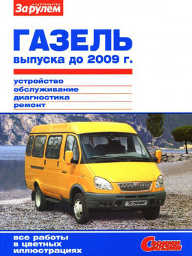
GAS 2705/3302 Gazelle until 2009, repair e-manual (in Russian)
About the manual
Engine type: UMZ-4216 ZMZ-40522
In the manual you will find
- Instructions for repair of various vehicle components
- Information on self-service car
- Information on the design of the car and how to prevent failure
- The information for the trip to the service station, if the self-repair is impossible
Content
Background
- Technical description
- Passport data of cars
- Maintenance and repair safety
Diagnosis of gazelle malfunctions
- Engine and its systems
- Clutch
- Transmission
- PTO, rear axle, chassis, steering and brake system
- Cab & body
- Rechargeable battery
- Generator
- Starter
- Lighting & signaling
UMZ-4216 Engine
- Design description
- Checking the oil level in the crankcase of the engine crankcase
- Oil and oil filter replacement
- Adjustment of thermal gaps in the valve actuator
- Removing the receiver
- Removal of intake pipe and exhaust manifold
- Removing the emergency oil pressure sensor sensor
- Replacing the cylinder head cover gasket
- Removing and disassembling the axis of the rocker arm
- Replacing oil reflector caps
- Removing the pusher box covers
- Removing the cylinder head
- Disassembly and assembly of the cylinder head
- Replacing the crankshaft front seal
- Replacing the crankshaft rear oil seal
- Removing the pallet pallet
- Oil pump removal and disassembly
- Dismantling of connecting rod and piston group by car
- Removing the fan drive belt tensioner
- Replacing power bearing supports
- Removing and installing the engine
- Disassembly and assembly of the engine
Engine management system UMZ-4216
- Design description
- Removing the electronic control unit
- Removing the crankshaft position sensor
- Phase sensor removal
- Throttle position sensor removal
- Removal of the inlet pressure and intake air temperature sensor
- Removing the coolant temperature sensor
- Detonation sensor removal
- Removing a rough road sensor
- Removing the speed sensor and its drive
- Removal of oxygen concentration control sensor
- Removal of the oxygen concentration diagnostic sensor
- Ignition coil removal
- Checking and replacing spark plugs
UMZ-4216 engine power system
- Design description
- Removing the fuel tank
- Removing and disassembling the fuel module
- Removal of fuel rail and injectors
- Idling regulator removal
- Removing the throttle assembly
- Throttle drive replacement
- Removal of the solenoid purge valve adsorber
- Removing the adsorber
UMZ-4216 engine cooling system
- Design description
- Fan drive belt condition check
- Replacing the fan drive belt
- Generator drive belt and coolant pump status check
- Alternator drive belt and coolant pump replacement
- Coolant replacement
- Removing and checking the thermostat
- Removing the radiator
- Removing the fan impeller
- Removing the fan switch electromagnetic clutch
- Removing the coolant pump
- Removing the expansion tank
The exhaust system of the UMZ-4216 engine
- Design description
- Removal of the receiving pipe
- Replacing the muffler
- Exhaust pipe replacement
ZMZ-40522 engine
- Design description
- Oil and oil filter replacement
- Oil pressure sensors removal
- Removing the receiver
- Inlet pipeline removal
- Removal of the exhaust manifold
- Replacing the crankshaft front seal
- Replacing the crankshaft rear oil seal
- Removal and installation of hydraulic loaders
- Camshaft removal
- Replacing pushers
- Removing and installing cylinder head
- disassembly and assembly of the cylinder head
- Valve lapping
- Disassembly of the valve actuator
- Disassembling the oil pump drive
- Replacing the power support front supports
- Removing the oil cooler
- Removing the engine from the car
- Disassembly and assembly of the engine
Engine control system ZMZ-40522
- Design description
- Engine control system malfunction codes
- Relays and fuses of the control system
- Removing the electronic engine control unit
- Removing the crankshaft position sensor
- Removing the mass air flow sensor
- Checking and replacing the throttle position sensor
- Phase sensor removal
- Detonation sensor removal and inspection
- Removing and checking the coolant temperature sensor
- Removal of the air temperature sensor in the inlet pipeline
- Checking and removing ignition coils
- Checking and replacing spark plugs
ZMZ-40522 engine power system
- Design description
- Replacing the air filter replacement element
- Replacing the fuel filter
- Throttle drive adjustment
- Fuel system pressure check
- Removal of fuel rail and injectors
- Nozzle check
- Replacing the fuel pressure regulator
- Throttle drive replacement
- Idling regulator removal and inspection
- Removing the fuel module
- Fuel pump replacement
- Replacing the fuel level meter sensor
- Removing the throttle assembly
ZMZ-40522 engine cooling system
- Design description
- Coolant replacement
- Removing the coolant pump
- Removing and checking the thermostat
- Removing the engine cooling system expansion tank
- Removing the radiator
- Replacing and adjusting the drive belt tension of the auxiliary units
- Replacing the temperature sensor and coolant overheating sensors
Clutch
- Design description
- Pumping of the clutch shut-off hydraulic actuator and replacement of the working fluid
- Removing the hydraulic master cylinder
- Removing the hydraulic drive cylinder
- Replacing the hydraulic hose
- Clutch crankcase removal (engine ZMZ-40522)
- Clutch crankcase removal (UMZ-4216 engine)
- Clutch pressure and slave disc removal
Transmission
- Design description
- Oil change
- Primary shaft bearing replacement
- Replacing the cuffs
- Replacing the reverse light switch
- Removing the gearbox
- Disassembly of the gearbox
Cardan gear
- Design description
- Inspection, inspection and lubrication of the driveshaft
- Removing the PTO
- Disassembly of the PTO
- Disassembling the universal joint
Rear bridge
- Design description
- Removing the rear wheels
- Gear oil change
- Shaft removal
- Wheel bearing adjustment
- Drive gear cuff replacement
- Wheel bearing and shaft seal replacement
- Removing the rear axle
- Rear axle disassembly
- Rear axle assembly and main gear adjustment
Front suspension
- Design description
- Removing the front wheel
- Oil seal grease
- Front wheel bearing adjustment
- Front wheel hub bearing replacement
- Removing, disassembling the spring and replacing it with rubber hinges
- Replacing the shock absorber
- Removing the front axle
- Disassembling the pin connection
Rear suspension
- Design description
- Removing, disassembling the spring and replacing it with rubber hinges
- Replacing the shock absorber
- Removal of rubber cushions for additional springs
Steering
- Design description
- Steering column adjustment
- Topping the oil in the crankcase
- lubrication of the cardan shaft joints
- Checking the technical condition of the steering
- Removing and disassembling the steering column
- Removing the steering gear without power steering
- Steering without adjusting the power steering
- Steering pump drive belt condition check
- Steering pump power belt replacement
- topping up the oil in the hydraulic booster system
- Oil and filter element replacement
- Pumping the steering hydraulic system
- Removing the hydraulic pump
- rinsing the hydraulic pump pump valves
- Pump cuff replacement
- Replacement of rotor, stator and pump seals
- Removing the steering gear with the power steering
- Adjustment of the steering mechanism with the hydraulic booster
- Replacing the power hose hoses
- Replacement of steering rods and their joints
- Front wheel alignment
Brake system
- Design description
- Pumping the brake system, replacing the brake fluid
- Replacing front wheel brake pads
- Front wheel brake replacement
- Replacing the brake disc
- Replacing the front brake hose
- Replacing the brake drum and rear wheel brake pads
- Rear wheel brake cylinder replacement
- Replacing the rear brake hose
- Removing the master brake cylinder
- Vacuum amplifier replacement
- Removing the pedal knot
- Adjustment and replacement of the pressure regulator
- Adjusting the parking brake actuator
- Parking brake drive cable replacement
- Disassembling the parking brake mechanism
- Replacing wheel speed sensors
- Replacing ABS hydraulic unit
Electrical equipment
- Design description
- Replacing fuses
- Rechargeable battery
- Replacing the battery switch
- Generator
- Generator removal and disassembly 3212.3771
- Removal of generator 3282m.3771
- Demolition of generator 3282m.3771
- Starter removal and verification
- Disassemble the starter
- Lighting, light and sound alarms
- Replacing the headlamp lamp
- Removing the headlamp
- Adjusting headlights
- Removing lateral turn signal, lamp replacement
- Replacing the brake signal switch
- Replacing the lamp, rear lamp removal
- Removing the license plate light, replacing the lamp
- Replacement of cabin and cabin lighting, ceiling removal
- Windscreen wiper and windshield washer
- Wiper removal & disassembly
- Control devices
- Removing the instrument cluster, replacing the lamps
Frame, cabin, body
- Design description
- Removing the front bumper
- Removing the radiator lining grid
- Removing the radiator panel front
- Removing the bonnet lock and its drive
- Removing the top panel of the radiator lining
- Removing the front fender
- Removing the rear exterior mirror
- Windshield replacement
- Removing the windshield rack upholstery
- Adjusting and removing the driver's seat
- Removal of passenger seats
- Removing the front seat belts
- Removing the seat belts of the second row of seats
- Removal of the sun visor
- Removing the door handle
- Removing the center rack upholstery
- Front door trim removal
- Removing the front door lock
- Front door glass replacement
- Window lift removal
- Removing the front door
- Removing the sliding door trim
- Removing the sliding door lock
- Replacing the sliding door and side windows.
- Removing the sliding door and dismantling its movement mechanism
- Removing the sliding door mechanisms
- Adjustable sliding door
- Removing the cab floor
- Removing ceiling upholstery
- Removing the cabin partition
- Removing the rear door lock
- Removing the rear door
- Removing the rear bumper
- Removal of the fuel filler filler hatch
- Removing and disassembling the dashboard
Ventilation and heating system
- Design description
- Replacement of the heater tap
- Removing the main heater radiator
- Replacing the main heater fan and resistor
- Removing the heating and ventilation control panel
- Removing the main heater
- Disassembly of the main heater
Applications
- Repair tools
- Tightening torques for threaded connections
- Arrangement of rolling bearings
- Rolling bearings
- Rubber reinforced seals (oil seals)
- Fuel, lubricants, and service fluids used
- Car lamps
Electrical equipment diagrams (electrical diagrams) Gazelle
- Engine control system diagram UMZ-4216, ZMZ-40522
- Electrical equipment diagram for vehicles with UMZ-4216, ZMZ-40522 engines
- Wire harness connection diagram for the UMZ-4216 engine control system (Euro 3)
- Electrical equipment diagrams for the anti-lock braking system


