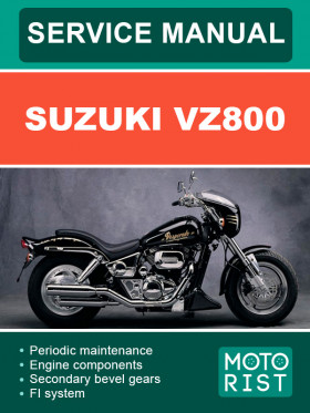
Suzuki VZ800, repair e-manual
Only original manuals
Available immediately after payment
Full compliance with the paper edition
100% protection of your payments
Publisher: © "Motorist"
ISBN: 978-115-441-267-0
Number of pages: 453
Format: file PDF
About the manual
Engine type: petrol
In the manual you will find
- Step-by-step guide to repair various components and assemblies
- Self-care and maintenance instructions
- Motorbike design and prevention information
- Information for a trip to the service station, if self-repair is not possible
Publisher:
Motorist
Only original manuals
Available immediately after payment
Full compliance with the paper edition
100% protection of your payments
Publisher: © "Motorist"
ISBN: 978-115-441-267-0
Number of pages: 453
Format: file PDF
About the manual
Engine type: petrol
In the manual you will find
- Step-by-step guide to repair various components and assemblies
- Self-care and maintenance instructions
- Motorbike design and prevention information
- Information for a trip to the service station, if self-repair is not possible
Content
General information
Periodic maintenance
- Periodic maintenance schedule
- Periodic maintenance chart
- Lubrication points
- Maintenance and tune-up procedures
- Air cleaner
- Spark plug
- Valve clearance
- Fuel hose
- Engine oil and oil filter
- Engine idle speed
- Throttle cable play
- Throttle valve synchronization
- Evaporative emisson control system (for e-33 only)
- Pair (air supply) system
- Clutch
- Cooling system
- Final gear oil
- Brake
- Tire
- Steering
- Front fork
- Rear suspension
- Exhaust pipe bolt
- Chassis bolt and nut
- Compression pressure check
- Compression test procedure
- Oil pressure check
- Oil pressure test procedure
- SDS check
Engine
- Engine components removable with engine in place
- Engine removal and installation
- Engine removal
- Engine installation
- Engine disassembly
- Engine components inspection and servicing
- Cylinder head cover
- Camshaft
- Cam chain tensioner and guide
- Cylinder head
- Cylinder
- Piston
- Conrod/crankshaft
- Clutch
- Generator/signal generator/ starter clutch
- Oil pump
- Transmission
- Gearshift fork
- Oil jet
- Crankcase
- Engine reassembly
Shaft drive
- Secondary bevel gears
- Construction
- Removal
- Disassembly
- Inspection
- Secondary gear shims adjustment
- Reassembly
- Installation
- Final bevel gears
- Construction
- Final gear case removal
- Final gear case disassembly
- Final gear shims adjustment
- Final gear case reassembly
- Final gear case installation
FI system
- Precautions in servicing
- Connector/coupler
- Fuse
- ECM/various sensors
- Electrical circuit inspection procedure
- Using the multi-circuit tester
- Fi system technical features
- Injection time (injection volume)
- Compensation of injection time (volume)
- Injection stop control
- Fi system parts location
- Fi system wiring diagram
- ECM terminal
- Self-diagnosis function
- User mode
- Dealer mode
- Tps adjustment
- Fail-safe function
- FI system troubleshooting
- Customer complaint analysis
- Visual inspection
- Self-diagnostic procedures
- Self-diagnosis reset procedure
- Use of SDS diagnostic procedures
- Use of SDS diagnosis reset procedure
- Show data when trouble (displaing data at the time of DTC)
- Malfunction code and defective condition
- “c12” (p0335) ckp sensor circuit malfunction
- “c13” (p1750) or “c17” (p0105) iap sensor circuit malfunction
- “c14” (p0120-h/l) TP sensor circuit malfunction
- “c15” (p0115-h/l) ECT sensor circuit malfunction
- ECT sensor inspection
- “c21” (p0110-h/l) iat sensor circuit malfunction
- “c23” (p1651-h/l) to sensor circuit malfunction
- “c24” (p0351) or “c25” (p0352) ignition system malfunction
- “c28” (p1655) STV actuator circuit malfunction
- “c29” (p1654-h/l) STP sensor circuit malfunction
- “c31” (p0705) GP switch circuit malfunction
Fuel system and throttle body
- Fuel delivery system
- Fuel system
- Fuel tank removal
- Fuel tank installation
- Fuel pressure inspection
- Fuel pump inspection
- Fuel discharge amount inspection
- Fuel pump relay inspection
- Fuel pump removal and disassembly
- Fuel mesh filter inspection and cleaning
- Fuel pump reassembly and installation
- Throttle body
- Construction
- Air cleaner box removal
- Air cleaner box installation
- Throttle body removal
- Throttle body disassembly
- Throttle body cleaning
- Inspection
- Throttle body reassembly
- Throttle body installation
- Stp sensor adjustment
- Fuel injector removal
- Fuel injector inspection
- Fuel injector installation
- Fast idle
- Fast idle adjustment
- Throttle valve synchronization
- Throttle position sensor (TPS) setting
Cooling and lubrication system
- Engine coolant
- Cooling circuit
- Cooling circuit inspection
- Radiator and water hoses
- Radiator removal
- Radiator cap inspection
- Radiator inspection and cleaning
- Radiator remounting
- Water hose and reservoir tank inspection
- Cooling fan
- Cooling fan thermo-switch
- Engine coolant temperature sensor
- Thermostat
- Water pump
- Lubrication system
- Oil pressure
- Oil filter
- Oil pressure regulator
- Oil strainer
- Oil jet
- Oil pump
- Oil pressure switch
- Engine lubrication system chart
Chassis
- Exterior parts
- Front wheel
- Front fork
- Handlebar
- Steering
- Steering tension adjustment
- Rear wheel
- Rear suspension
- Rear shock absorber disposal
- Suspension setting
- Front brake
Electrical system
- Cautions in servicing
- Connector
- Coupler
- Clamp
- Fuse
- Semi-conductor equipped part
- Battery
- Connecting the battery
- Wiring procedure
- Using the multi-circuit tester
- Location of electrical components
- Charging system
- Starter system and side-stand/ignition interlock system
- Starter motor
- Starter relay inspection
- Side stand/ignition interlock system parts inspection
- Ignition system
- Speedometer and pilot lamp box
- Lamps
- Headlight, brake light/taillight, license plate light and turn signal light
- Relays
- Turn signal/side-stand relay
- Starter relay
- Fuel pump relay
Servicing information
- Troubleshooting
- Fi system malfunction code and defective condition
- Engine
- Radiator (cooling system)
- Chassis
- Shaft drive
- Brakes
- Electrical
- Battery
- Wiring harness, cable and hose routing
- Wiring harness routing
- Cable routing
- Throttle body installation
- Cooling system hose routing
- Front brake routing
- Speed sensor harness routing
- Front turn signal installation
- Front turn signal lead wire routing
- Muffler and exhaust pipe installation
- Handlebar balancer
- Battery protector
- Lubrication points
- Fuel tank installation
- Rear combination lamp installation
- Frame head cover cushion installation
- Left side cover cushion installation
- Rear fender cushion installation
- Left side cover installation
- Lid cushion instsallation
- Tail lamp installation
- Pair (air supply) system diagram
- Pair (air supply) system hose routing
- Special tools
- Tightening torque
- Engine
- Secondary and final
- Fi system and intake air system
- Cooling system
- Chassis
- Tightening torque chart
- Service data
Emission control information
- Emission control systems
- Fuel injection system
- Exhaust emission control system (pair system)
- Noise emission control system
- Evaporative emission control system (only for e-33)
- Pair (air supply) system inspection
- Hoses
- Pair reed valve
- Pair control solenoid valve
- Pair (air supply) system hose routing
- Heated oxgen sensor (ho2s) inspection (for e-02, 19, 24)
- Evaporative emission control system inspection (only for e-33)
- Hoses (EVAP hose)
- EVAP canister
- EVAP canister hose routing (only for e-33)
Wiring diagram
Write a review
Your Name:
Your Review:
Customers reviews
I was able to do my own maintenance on my bike. All clear. Now next in line is the repair of the fuel system. I think I can handle it


