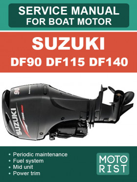
Suzuki outboard motor DF90 / DF115 / DF140, repair e-manual
About the manual
Engine type: Suzuki DF90 / DF115 / DF140
In the manual you will find
- Step-by-step guide to repair various components and assemblies
- Self-care and maintenance instructions
- Boat motor design and prevention information
- Information for a trip to the service station, if self-repair is not possible
Content
Periodic maintenance
- Periodic maintenance schedule
- Maintenance and tune-up procedures
- Oil pressure
- Cylinder compression
Engine control system
- Engine control system structure
- Components for system control
- Ignition system
- Electronic fuel injection system
- Caution system
- Self-diagnostic system
- Fail-safe system
- Operating hour indication system
- Oil change reminder system
- Start-in-gear protection system
- Feedback system
- Inspection
- Troubleshooting
- Removal / installation
Electrical
- Battery charging system
- Electric starter system
- Monitor-tachometer
- Electric parts holder
Wire / hose routing
- Wiring diagram
- Wire routing
- Fuel / water hose routing
Fuel system
- Precaution on fuel system service
- Fuel line
- Fuel vapor separator / high pressure fuel pump
- Fuel injector
- Low pressure fuel pump
- Tank
Power unit
- Intake manifold assembly
- Power unit
- Oil pump
- Timing chain / tensioner
- Cylinder head assembly
- Cylinder / crankshaft / piston
- Thermostat
- Operation
Mid unit
- Engine side cover
- Driveshaft housing and oil pan
- Swivel bracket, steering bracket and clamp bracket
- Water pressure valve
Power trim and tilt
- System wiring diagram
- Service procedure
- Power trim and tilt unit
- PTT motor relay
- PTT switch
- Operation
Lower unit
- Removal and disassembly
- Pinion bearing
- Inspection
- Assembly and installation
- Trim tab
- Lower unit gears-shimming and adjustment
DF140 “K2” (’02) model
- General information
- Engine control system
- Power unit
- Mid unit
- Power trim and tilt
- Lower unit (normal rotation model)
- Counter rotation lower unit (DF140Z)
- Wiring diagra
- Hose routing
DF90 / 115 “K2” (’02) model
- Specifications
- Service data
- Tightening torque
- Materials required
- Fuel/water hose routing
- Over-revolution caution system
- Crank pin and conrod bearing
- Conrod assy and bearing
- Crankshaft and flywheel
- Camshaft and tappet shim
- Engine holder gasket
- Engine holder bolt
- Upper mount front nut
- Clutch linkage
DF90 / 115 / 140 “K3” (2003) model
- Specifications
- Service data
- Tightening torque
- ECM
- ECM main relay and starter motor relay
- Battery charge coil
- Rectifier and regulator
- Exhaust cam shaft (for DF115 only)
- Remote control cable holder
- Cylinder head instllation
- Crankcase to cylinder instllation
- Upper mount
- Drive shaft
- Propeller shaft bearing housing
- Wiring diagra
- Water hose routing
DF90 / 115 / 140 “k4” (’04) model
- Specifications (DF90T / 115T / 115WT)
- Specifications (DF140T / 140WT / 140Z)
- Service data (DF90 / 115)
- Service data (DF140)
- Temperature sensor
- Cylinder block
- Rectifier and regulator
- Power trim and tilt (P.T.T.) relay
- Electric parts holder
- P.T.T. Motor
- Tilt limit switch system
- Swivel bracket
- Clamp bracket shaft
- Port clamp bracket
- Driveshaft
- Pinion gear back up shim
- Lower unit gears-shimming and adjustment
- Wiring diagram
DF90 / 115 / 140 “k5” (2005) model
- Specifications (DF90T / 115T / 115WT)
- Specifications (DF140T / 140WT / 140Z / 140WZ)
- Service data (DF90T / 115T / 115WT)
- Service data (DF140T / 140WT / 140Z / 140WZ)
- Engine wiring harness
- Safety relay system
- ECM
- Sub-battery cable
- Remote control box and remote control wire
- Tilt limit switch cover
- Piston oil ring
- Tensioner adjuster
- Engin holder
- Upper and lower mount
- Transom bolt
- Wire / hose routing
- Wiring diagram
DF90/115/140 “K6” (2006) model
- Specifications (DF90T / 115T / 115WT)
- Specifications (DF140T / 140WT / 140Z / 140WZ)
- Service data (DF90T / 115T / 115WT)
- Service data (DF140T / 140WT / 140Z / 140WZ)
- Tightening torque
- Periodic maintenance schedule
- ECM
- Neutral switch
- Fuel filter
- Delivery pipe
- Oil strainer
- Oil cooler (for DF140)
- Engine holder and cylinder block
- Cltuch link
- Swivel bracket bushing grease path
- Clamp bracket (for DF90 AND DF115)
- Swivel bracket
- Steering bracket
- Upper mount
- Water pump
- Water pump tube
- Exhaust seal rubber
- Shift rod guide housing
- Shift rod, shifter yoke and horizontal slider
- Drive shaft
- Propeller shaft and connector pin
- Forward gear and clutch dog
- Wiring / hose routing
- Wiring diagram
DF90 / 115 / 140 “K7” (2007) model
- Specifications (DF90T / 115T / 115WT)
- Specifications (DF140T / 140WT / 140Z / 140WZ)
- Service data (DF90T / 115T / 115WT)
- Service data (DF140T / 140WT / 140Z / 140WZ)
- Periodic maintenance schedule
- ECM
- Fuel hose, cable grommet and front panel
- Pinion / gear set
DF90 / 115 / 140 “K8” (2008) model
- Specifications (DF90T / 115T / 115WT)
- Specifications (DF140T / 140WT / 140Z / 140WZ)
- Service data (DF90T / 115T / 115WT)
- Service data (DF140T / 140WT / 140Z / 140WZ)
- Periodic maintenance
- Engine control system
- Digital gauge system
- Engine holder
- Wiring diagram
- Wire routing
DF100 “K9” (2009) model
- General information
- Engine control
- Power unit
- Wire / hose routing


