Our books can be purchased by cards єPidtrimka!

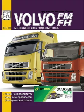
Volvo FH / FM until 2005, fault codes, troubleshooting and wiring diagrams (in Russian), volume 3

How to pay and download
Only original manuals
Available immediately after payment
Full compliance with the paper edition
100% protection of your payments
(9)
9 10 1
Publisher: © "Diez"
ISBN: 978-5-903883-99-8
Number of pages: 464
Format: file PDF

About the manual

Engine types: D9B / D13A

Engine capacity: 9.4 / 12.8 l.

Power: 300 / 340 / 360 / 380 / 400 / 440 / 480 / 520 hp

In the manual you will find

  • Instructions for repair of various vehicle components
  • Information on self-service car
  • Information on the design of the car and how to prevent failure
  • The information for the trip to the service station, if the self-repair is impossible
Publisher: Diez
Categories: Trucks , Volvo
Only original manuals
Available immediately after payment
Full compliance with the paper edition
100% protection of your payments
Publisher: © "Diez"
ISBN: 978-5-903883-99-8
Number of pages: 464
Format: file PDF

About the manual

Engine types: D9B / D13A

Engine capacity: 9.4 / 12.8 l.

Power: 300 / 340 / 360 / 380 / 400 / 440 / 480 / 520 hp

In the manual you will find

  • Instructions for repair of various vehicle components
  • Information on self-service car
  • Information on the design of the car and how to prevent failure
  • The information for the trip to the service station, if the self-repair is impossible

In the third volume are considered:

  1. - troubleshooting data
  2. - trouble codes
  3. - electrical diagrams;

Contents

Troubleshooting

  • Engine
  • Engine fault codes
  • Symptomatic engine troubleshooting
  • Black smoke
  • Blue smoke
  • White or gray smoke
  • High fuel consumption
  • Fuel in engine oil
  • Mixing engine oil with coolant
  • Low power output
  • Troubleshooting, intermittent failures
  • Sudden loss of power
  • Gradual loss of power
  • The engine does not reach the set speed
  • Low engine power output after vehicle repair
  • Unstable engine performance
  • Unstable engine idling
  • Unstable engine speed at low or high idle speed
  • Engine runs erratically or misfires
  • Unstable engine speed under load
  • Engine speed increases when PTO or cruise control is engaged
  • Noise and vibration
  • Troubleshooting
  • Noise and vibration symptoms
  • Component compliance check
  • Transmission
  • Mechanical clutch, symptomatic troubleshooting
  • Transmission VT 1906 RT
  • Transmission VT 2206 RT
  • Transmission VT 2412 B
  • GEARTRONIC gearbox
  • Torque converter transmission
  • Overview of transmission trouble codes
  • Steering
  • Steering symptom troubleshooting
  • Fault codes
  • Checking the axial play of the ball joints of the longitudinal and transverse steering rods
  • Brake system
  • Brake system malfunction codes
  • Fault codes for compact retarder
  • Overview of brake system trouble codes
  • Air system check list
  • Air dryer
  • Dehumidifiers AIRDRY option 2
  • Compressor
  • Compressors 1COMP530, 2COM1080 option 2
  • Air dryer
  • Suspension
  • Pneumatic suspension
  • Air suspension fault codes overview
  • Troubleshooting the electronically controlled ECS air suspension
  • Body, cab and interior
  • Seat, belt tensioner
  • Heater
  • Symptomatic troubleshooting
  • Air heater malfunctions
  • Fuel pump
  • AIR top 2000s fault codes
  • Fault code overview
  • Electrical equipment
  • Battery
  • Fault codes, VECU (electronic vehicle control system)
  • Instrument cluster fault codes
  • Air suspension fault codes overview

Electrical diagrams

  • Wiring diagrams of VOLVO FH12 and FH16 cars (up to September 1998)
  • Wiring diagram example
  • Examples of electrical symbols
  • Letter codes of designations of electrical systems on electrical diagrams
  • AA diagram: power supply, starting system, immobilizer
  • Wiring diagrams
  • AC diagram: vehicle ECU control unit
  • BL diagram: engine control unit ECU, injection system, preheater, FH12
  • BN diagram: engine control unit ECU, injection system, preheater, FH16
  • CE diagram: headlights, parking light, parking lights, DRL
  • CG diagram: fog lights, rear fog lights
  • Diagram CH: additional turning lights (STD) DRIVL2
  • CI diagram: two additional cornering light bulbs for low positioning cornering lights (EU) DRIVL2EC
  • CK circuit: brake signal
  • CL diagram: engine brake
  • CN diagram: direction indicator, alarm
  • EA diagram: reversing lighting, buzzer
  • Diagram ED: loading lighting, towing lighting
  • Diagram EJ: roof light, L1H1 / L2H1
  • Scheme EK: roof light, L2H2
  • Diagram EN: Signal light
  • ER scheme: interior lighting, L1H1 / L2H1, alarm / timer
  • ES scheme: interior lighting, L2H2 / L2H3, alarm / timer
  • EV diagram: cigarette lighter
  • FA circuit: beep (beep)
  • EX schematic: 12V power supply
  • GA scheme: wiper, washer
  • HA diagram: climate control
  • HB diagram: cab heater, eberspächer D1LCC, PH-CAB
  • HC schematic: cab and engine heater, WEBASTO THERMO 90, PH-ENGCA
  • Diagram HE: electrically heated and adjustable seat
  • HG diagram: electrically heated mirrors
  • Diagram HH: electrically controlled mirrors
  • HK diagram: air dryer
  • HM Diagram: fuel filter heater
  • HO Diagram: water separator heater
  • HP Diagram: electric cab tilt system
  • Scheme JA: radio
  • KA diagram: electric windows
  • Sketch KB: electric sunroof
  • KE diagram: SRS (SUPPLEMENTAL RESTRAINT SYSTEM) airbag
  • KH scheme: central door lock
  • LD diagram: PTO
  • LE scheme: dual power take-off
  • LG Diagram: differential lock
  • LJ diagram: lifting and securing additional axle, RADT-LA
  • LL diagram: securing additional bridge, RADT-A6S
  • MA diagram: hydraulic auxiliary axle lift, RADT-AR
  • MD Diagram: hydraulic auxiliary axle lift, load limiting, RADT-AR
  • ME diagram: air suspension, 6x2 / 6x4 / 8x2 / 8x4, SUSPL-EC
  • MF diagram: air suspension, 4x2, SUSPL-EC
  • MG diagram: rear axle air suspension, 4x2, TRACTOR, SUSPL-EC
  • Diagram NA: Instrument Cluster (Left Hand Drive)
  • NB diagram: central instrument cluster with tachograph
  • NC diagram: instrument cluster (right hand drive)
  • Diagram NZ: central instrument cluster without tachograph
  • OA diagram: ABS, D-modification
  • OB diagram: ABS / ASR, D-modification
  • PA diagram: headlight level control
  • TB diagram: central lubrication system
  • TA diagram: refrigerator
  • XA diagram: fuses, key relays
  • ZA diagram: earth connections
  • ZB diagram: earth connections
  • ZD diagram: ADR, battery main switch, current limiter
  • Diagram ZE: air heater EBERSPÄCHER TMD, ADR-FRA
  • Electrical harness
  • Ground connections
  • Battery cables
  • Posting
  • Arrangement of elements on the distribution panel
  • Fuses on the distribution panel
  • Distribution panel relay
  • Connector List
  • List of components
  • Wire color codes
  • Abbreviations
  • Wiring diagrams of VOLVO FM9, FM12, FH12, FH16, NH12 cars (before September 2005)
  • Wiring diagram example
  • Letter codes for designations of electrical systems on electrical circuits
  • Electrical diagrams
  • Cable harnesses
  • Wire harnesses
  • Fuses
  • Relay
  • Cable harnesses
  • Mass connections
  • Layout of elements
  • Ground connection points
  • Connectors
  • Components
  • Wire color codes
  • Abbreviations

Write a review

Your Name:
Your Review:
Rating:

Customers reviews

Искал схему проводки головного освещения, удалось найти только на этом сайте хотя и за деньги.....В интернете попадаются схемы или плохого качества или какая то ерунда. Только время зря потратил, лучше сразу здесь купить